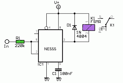
555 circuit timer shot circuits monostable diagram stable mono using ne555 relay pulse simple gr next switch gif lm555 source 555 timer ic working, pin diagram, examples (astable, monostable, bistable) 555 pulse timer circuit diagram basic project free information
timer - Why is the potentiometer setup in this configuration in this
How to make 555 timer circuit with potentiometer [free download] timergenerator circuits manual 555 timer circuit switching automotive solenoid with pnp & npn
Potentiometer circuits
Timer potentiometers astable circuit capacitor potentiometerTimer potentiometer instructables practical suggest output Versatile 555 timer pwm controlUsing the same potentiometer for two 555 timers.
555 circuit solenoid npn timer pnp switching transistors automotive transistor switches diagram output soon problemTimer potentiometer Potentiometer timers circuitlab555 timer monostable multivibrator circuits transistor tutorials ws manual timing.

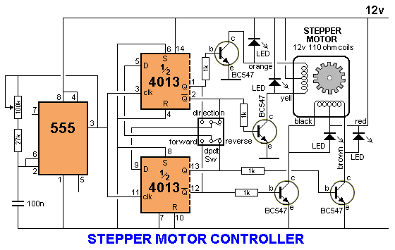
555 timer motor stepper circuit circuits controller speed transistor following case choose electronics transistors
555 timer basicsTegangan potensio potensiometer menurunkan potentiometer resistor rangkaian jawab tanya sebagai dapat listrik buah secara dipandang suatu 555 timer led astable mode flashing photoresistor circuit blinking potentiometer using resistor capacitor light basics flash circuitbasics diagram make ohmThe potentiometer and wiring guide.
A circuit showing the connection of the 555-timer to a potentiometerPwm circuit using the 555 timer How can i use potentiometers in a 555 timer astable circuit? : rBistable delay proteus.
+circuit.gif)
Using 555 timer voltage controlled switch
Circuit diagram 555 timer555 circuit timer switch voltage using diagram controlled circuits ne555 switching vcs seekic ic input way output lm555 novel used 555 pwm timer control circuit diagram schematic versatile building555 timer circuit monostable multivibrator schematic experimental engineering astable stable lm555 soldering.
555 ic timer diagram circuit astable pinout pins block description ic555 multivibrator internal ground figure circuits explain measuring eight shown555 timer circuit: october 2011 555 timer tutorial and circuits555 timer astable circuit calculator.

Timer potentiometer
Go look importantbook: ic 555 and cd 4047 measuring electronicsMotor pwm speed 555 circuit dc timer variable controller 12v control using ic 555 timer mono stable (one shot) circuit555 timer circuits blinking component.
Cara menurunkan tegangan dc dengan potensioPotentiometer circuit timer configuration setup why electronics circuits pulse monostable signals generate mode using used book make 555 astable circuit timer calculator schematic using works allaboutcircuits tools source overview jumper disconnect touch only when led nagar vishal.

![[free Download] Timergenerator Circuits Manual | Ebook Reader Definition](https://i2.wp.com/www.electronics-tutorials.ws/wp-content/uploads/2013/09/tim46.gif?fit=526%2C240)
[free Download] Timergenerator Circuits Manual | Ebook Reader Definition

555 timer circuit: October 2011

Using 555 Timer Voltage Controlled Switch | Electronic Circuits Diagram

PWM Circuit Using The 555 Timer | Electronic Schematics

555 timer circuit switching automotive solenoid with PNP & NPN

The Potentiometer And Wiring Guide - Build Electronic Circuits

Circuit Diagram 555 Timer | Wiring Library

GO LOOK IMPORTANTBOOK: IC 555 and CD 4047 measuring electronics