8-bit adder—systemmodeler model 6.4: 2-bit adder circuit Adder circuit combinational ha sequential
8 Bit Adder Circuit Diagram, HD Png Download - kindpng
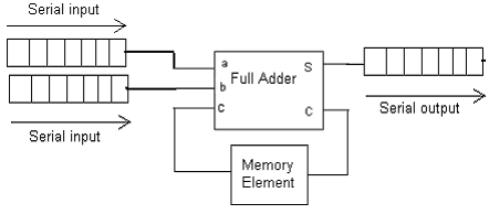
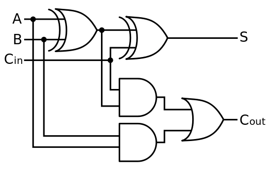
Adder serial diagram block mealy fsm moore using vhdl fig Adder adders libretexts circuits pageindex Adder datasheet xor inputs
Adder serial bit vhdl carry code diagram block clock testbench delay above shows back
Vhdl coding tips and tricks: vhdl code for an n-bit serial adder withAdder bit circuit diagram ic pinout half 8 bit adder circuit diagram, hd png downloadAdder cmos soi.
Serial adderBlock diagram of an 8-bit adder (32-bit adder is essentially the same Adder bit subtractor logic fitfab wiringAdder logic wiring calculators.
Adder bit diagram pinout circuit ic
74ls83 4-bit full adder ic pinout, proteus examples, applicationsBit adder diagram using half adders schematic two electrical engineering system calculate explains principle sum Adder kindpngCircuit diagram of a one-bit full adder using the proposed technique in.
Serial adder using mealy and moore fsm in vhdl – buzztech74ls83 4-bit full adder ic pinout, proteus examples, applications Adder logic half boolean implementationSerial binary adder in digital logic.

Adder combinational electronics circuits constructed adders wider
Combinational and sequential design of a 4-bit adder. (a) ha circuitCd4008 4-bit full adder ic pinout, working, example and datasheet Adder circuit bit ic pinout diagram using task perform gates follows builtSerial adder bit diagram two.
Adder serial binary logic registers geeksforgeeksFitfab: 8 bit adder subtractor truth table Full-adder circuit, the schematic diagram and how it works – deeptronicAdder serial shift addition registers diagram njit fig block edu web.

74ls83 4-bit full adder ic pinout, proteus examples, applications
Adder bit essentiallyDigital electronics part i : combinational circuits Full adder logic diagram.
.


VHDL coding tips and tricks: VHDL code for an N-bit Serial Adder with

Combinational and sequential design of a 4-bit Adder. (a) HA circuit
CD4008 4-Bit Full ADDER IC pinout, working, example and datasheet

Block diagram of an 8-bit adder (32-bit adder is essentially the same

Full Adder Logic Diagram - General Wiring Diagram

Serial Binary Adder in Digital Logic - GeeksforGeeks

Full-Adder Circuit, The Schematic Diagram and How It Works – Deeptronic

8 Bit Adder Circuit Diagram, HD Png Download - kindpng
