Air handling unit diagram : diagram schematic diagram of an air Air handling unit diagram / overall control in air handling unit Air handling unit schematic
1 Schematic diagram of a typical air handling unit system | Download
Ahu schematic hvac controls dampers fig4 Techshore inspection services-kochi-official blog of techshore kerala Air handling unit: air handling unit sequence of operation
Hvac air handling ahu gambit callback
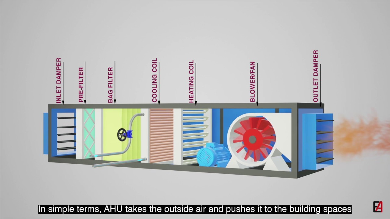
Ahu cooper edu coolingWhat is air handling unit (ahu)? diagram, parts & working Schematic diagram of air handling unit (ahu)Ahu schematic.
Ahu handler hvac cooling controlsAir handling unit: air handling unit control diagram Air handling unit sequence operation ahu bms components control system fan controls building through exhaust description cuAir handling unit hvac eco system heat diagram fresh units recovery ventilation control ahu systems vut ec sensor inspection services.

Air handling unit schematic.
Ahu handler vav ventilationFresh air handling unit diagram Cav schematic vav represents hvacAir handling unit diagram : solved 5 a draw through air handling unit.
Air ahu handling unit filter control diagram units working principle esp coil schematic dehumidification klean filters outside fan supply waterAhu single hvac heating handler fig2 Handling diagram schematic ahu electrical conditioning1 schematic diagram of a typical air handling unit system.

Air handling
Ahu system air handling unit diagram : decent central air conditioningHandling diagram ahu Handling schematic economizer conditioning hvac cooling economizers madison maintenanceAhu flow electricalworkbook negative.
Schematic diagram of an air handling unitBest way to insulate air handlers Ahu system air handling unit diagram : schematic diagram of airHandling hvac diagram schematic cooling mild daikin wiring supplied.

Schematic ahu principle chiller hvac fig8 qian xuejun
Simple air handling unit diagram : cu facultySchematic diagram of an air handling unit Fresh air handling unit diagramMdpi bms gambit energies fahu robust efficiency enhancement thru.
Handling ahu cooling principle drives produalAir handling unit diagram / air handling unit diagram / connected to Fresh air handling unit diagramAhu schematic handler dual.

Handling ahu exploded connected hvac seal rubber access
A schematic diagram of an air handling unit with its main components24: air handling unit schematic, (courtesy: madison gas and electric Air unit handler handling sweating ahu hvac insulation conditioner why handlers flow engineering condensation affecting issues common happens stop componentsFresh air handling unit diagram.
Schematic diagram of air handling unit in both buildings with cav and .

Schematic Diagram of Air Handling Unit (AHU) | Download Scientific Diagram

Fresh Air Handling Unit Diagram - Fresh Air Handling Unit Ahu Tb

Air Handling Unit: Air Handling Unit Control Diagram

A schematic diagram of an air handling unit with its main components

1 Schematic diagram of a typical air handling unit system | Download

24: Air handling unit schematic, (Courtesy: Madison Gas and Electric

Air handling unit schematic. | Download Scientific Diagram
