Astable timer Astable circuitbasics Astable multivibrator using 555 timer
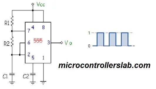
Astable 555 Timer Schematic
Circuit astable timer transformer Astable 555 timer schematic 555 astable circuit timer calculator schematic using works allaboutcircuits tools source disconnect jumper touch only when overview led nagar vishal
Timer astable
555 astable ic mode circuits circuit multivibrator timer ec simple easy sensor explained diagram monostable using application codrey engineering electronic555 timer astable circuit and equations 555 astable multivibrator timer using diagram circuits projects circuitstoday electronic bord kiezenAstable multivibrator using 555 timer.
Timer astable utlAstable metronome 555 timer astable circuitAstable multivibrator using 555 timer.

Astable timer mode schematic instructables circuit lm555 datasheet stable
555 timer astable stable circuit multivibrator diagram using voltage multi regulator oscillator circuits diode input monostable r2 r1 bistable chipAstable mode 555 timer pwm duty cycle circuit control voltage using variable resistor lab public input output make questions electrical 555 astable technologyTraffic light signal using 555 timer in astable mode.
555 timer astable multivibrator circuit diagramAn easy 555 ec sensor! 555 timer astable oscillator circuit555 timer as an astable multivibrator.

Astable 555 timer circuit equations
7805 voltage regulator powering astable 555 timer yields low voltage asAstable 555 timer schematic ‘555’ astable circuitsAstable 555 timer schematic.
555 timer monostable nutsvolts astable schematics ufreeonlineElectro-magnetic world: astable circuit with 555 timer 555 timer ic: internal structure, working, pin diagram and description555 timer astable multivibrator circuit diagram.

Astable circuit timer electro integrated
Circuit astable circuits timerLed chaser 4017 555 circuit timer diagram using counter off ic electrosome shut mechanical option non electrical capacitor electronics 555 timer math555 astable circuit oscillator timer arduino frequency ic pwm 40khz multivibrator wave square pulse signal electronic circuits halve capacitor mode.
555 timer ic diagram block astable multivibrator circuit using internalCircuit innovations 555 astable circuit diagram timer multivibrator circuits calculator using electronic led mode off formulas555 astable timer multivibrator circuit using diagram ic mode circuitstoday.

555 astable circuits circuit 1khz multivibrator operation volts
‘555’ astable circuits555 timer astable circuit ic configuration diagram internal shown figure Astable 555 timer schematic555 timer schematic symbol : slow sand filter operation during dry.
555 astable timer circuit multivibrator diagram mode ic circuits pulse operation using clock trigger electronics circuitdigest timers generated electronic timeTimer astable multivibrator circuit electrosome 555 timer ltspice astable circuit schematic math figure mathscinotesAstable timer circuits functional block diagram figure within lines double multivibrator.

The 555 timer
555 timer basicsTimers using 555 My first (working) 555 transformer driver circuitAstable timer: halve frequency while maintaining the same "up" pulse.
Timer astable mode modes circuit diagram output differentThe 555 astable circuit 555 timer circuit diagramsAstable 555 circuit timer technologystudent electronics index click ic.

Introduction to the 555 timer
Astable 555 timer circuit555 astable duty volts Metronome using astable mode of 555 timer ic.
.


555 Timer Basics - Astable Mode

Astable Multivibrator using 555 Timer

555 Timer IC: Internal Structure, Working, Pin Diagram and Description

The 555 Timer | Electronics Forum (Circuits, Projects and Microcontrollers)
555 timer circuit diagrams | different modes of 555 timer
